
Support
How can we help you today?
How the safety check of missing ground is done in OpenEVSE

OpenEVSE Support
A small current is run through an opto-isolator from each hot to ground. This lights up the internal LED, a detector on the low voltage side tells the microprocessor that the current is flowing.
If the path to ground is broken anywhere between the station and the earth rod in your home, the LED will not illuminate and the microprocessor will prevent or stop charging.
The feature is required by UL to ensure there is always a path to ground so a short will trip GFCI. A broken ground plus a short to the chassis would cause the whole station and vehicle to be at line level.
The American split-phase system uses two optocouplers, each connected between a phase and ground. In the European system, this approach does not work the same way.
An optocoupler connected between a phase and ground will trigger; however, the voltage between the neutral (N) conductor and ground is typically between 0V and a few volts, which is insufficient to activate an optocoupler.
Consequently, the relay on the neutral line cannot be monitored.
Connecting an optocoupler between the phase and neutral is also not a viable solution; while it would indeed trigger, it would fail to detect a situation where one of the two relays has not switched. And that does not monitor the PE.
The resistance of the optocoupler between the 240V phase and ground must also be chosen to be higher than in the US. In Europe, a single phase is 220 to 240 V; in the US, it is 120 V.
Furthermore, in Europe, the GFCI (RCD) must be rated for 30 mA AC or 6 mA DC.
20 mA AC GFCIs are not suitable.
In Europe, all cables connected to the vehicle feature a fixed resistor at the PP (Proximity Pilot) pin within the connector. OpenEVSE is unable to monitor the PP signal.
It can only monitor the CP (Control Pilot) signal.
openEVSE uses a 200kΩ resistor for the optocouplers. At 240V between phase and ground, this results in a current of 1.2 mA. However, the voltage rating of a single resistor is often only 200V—and even lower for SMD components.
OpenEVSE Support
@Jens the older boards used fairly large threw hole flameproof resistors with a higher voltage ratings. The current design v6.5.1 uses 4 strings of two each 1210 160k (AC_Input and AC_Test channel) for the voltage rating.
OpenEVSE Support
@Jens Incorrect - OpenEVSE does have a PP (Proximity Pilot) input and can monitor BOTH PP and CP (Control Pilot).
Yes, that’s correct. OpenEVSE monitors the CP signal and the PP resistor on the circuit board.
However, there is no connection between the board and the Type 2 plug. (Europe)
The PP resistor—which the car detects—is located inside the Type 2 plug itself; because there is no corresponding wire, it cannot be connected to the OpenEVSE board.
A Type 2 cable contains conductors for 1 or 3 phases, neutral, ground, and the CP signal, but it does not include a line for the PP signal.
In Europe, the PP (Proximity Pilot) resistance—220Ω (for 32A) or 680Ω (for 20A)—is permanently integrated into the Type 2 connector and does not change. There is no button on the Type 2 connector. An exception exists for some Tesla fast chargers, though these do not comply with the European standard.
OpenEVSE can measure a fixed resistance—either 220Ω or 680Ω—on the circuit board and use this to set the maximum current.
However, OpenEVSE cannot detect when the key fob button is pressed and the connector is unlocked.
This takes place via the CP signal.
Using several large resistors in series is the right approach. This is how all devices in Europe that detect mains voltage do it.
OpenEVSE Support
@Jens I would suggest you do more research you are confusing J1772 Proximity and IEC Proximity Pilot.
OpenEVSE supports BOTH. In a socketed (non-teathered) Type 2 cable OpenEVSE DOES read the PP resistor in the EVSE socket side plug and will set the pilot accordingly based on the IEC defined resistance. In a teathered Type 2 cable there is no need to read PP, the cable is physically teathered and does not change like a socketed bring your own cable setup.
For J1772 proximity there is no wire to OpenEVSE this is vehicle side only.
Your statement the OpenEVSE does not support IEC PP in Europe is absolutely incorrect.
OpenEVSE Support
In Europe, all cables connected to the vehicle feature a fixed resistor at the PP (Proximity Pilot) pin within the connector. OpenEVSE is unable to monitor the PP signal.
Incorrect. OpenEVSE is able to monitor PP signals just fine on a Type 2 Socket.
It can only monitor the CP (Control Pilot) signal.
Incorrect. OpenEVSE can monitor BOTH CP and PP.
As I said, in Europe, the PP (Proximity Pilot) is statically integrated into the connector. OpenEVSE uses a voltage divider consisting of a fixed 10kΩ resistor and a 680Ω resistor. That just means the cable can handle 20A. There is no switch on the connector—(except in the case of Tesla Superchargers, works with Tesla EV only)
In Europe, the plug is released using the key fob. Signaled via CP. The voltage rises to 12V.
In the US, however, there is a switch on the PP line that uses various resistance values and a switch. In that context, it makes sense to measure the voltage
I am confident that OpenEVSE can measure the fixed 10k/680R voltage divider in Europe.
However, this never changes and determines the maximum current.
Correction to the statement:
5V –> 1k / 680Ω.
The 10k resistor is in series with the M328P, and the diode is oriented in the reverse direction.
OpenEVSE Support
As I said, in Europe, the PP (Proximity Pilot) is statically integrated into the connector. OpenEVSE uses a voltage divider consisting of a fixed 10kΩ resistor and a 680Ω resistor. That just means the cable can handle 20A. There is no switch on the connector—(except in the case of Tesla Superchargers, works with Tesla EV only)
In Europe, the plug is released using the key fob. Signaled via CP. The voltage rises to 12V.
Incorrect again... the OpenEVSE PP analog circuit has a 1k resistor to vcc and 10k to the analog pin then a protection diode to ground. This is a general purpose analog circuit to read a EXTERNAL resistance It can read and set all of the PP resistance below:
| Cable Current Rating | Nominal Resistance |
|---|---|
| 13 A | 1.5 kΩ (1,500 Ω) |
| 20 A | 680 Ω |
| 32 A | 220 Ω (often toleranced/listed around 200 Ω–220 Ω) |
| 63 A (3-phase) / 70 A (1-phase) | 100 Ω |
In addition to the above resistance, the OpenEVSE PP code also reads for a open or short and provides the appropriate errors.
The switch on the cable is compleetly different it is not related to Proximity Pilot PP at all other than the similar name Proximity. The button press is NOT signaled over CP and the voltage does not rise to 12v, the button press signals to the VEHICLE to stop pulling current. A State C (6v) to State B (9v) may happen shorlty after when the vehicle is no longer charging but the resistance that pulls 12v down to 9v is fixed into the J1772 socket. The State B (9v) to State A (12v) CP voltage has nothing to do with the proximity button the change happens when the fixed resistor is disconnected by physical plug removal.
In the US, however, there is a switch on the PP line that uses various resistance values and a switch. In that context, it makes sense to measure the voltage
Still incorrect - The switch is on Proximity (NOT PP) between the plug and vehicle, voltage is not measured by OpenEVSE for J1772 proximity (NOT PP). PP lines do not exsist in J1772. Similar name COMPLEETLY different function.
I am confident that OpenEVSE can measure the fixed 10k/680R voltage divider in Europe.
However, this never changes and determines the maximum current.
Incorrect OpenEVSE does read any of the IEC resistance values, determines ampacity and does set the maximum current. In fact the circuit can measure any resistance with precision, the latest OpenEVSE code allows the unused (in the US and on teathered Europeen stations) PP circuit to measure NTC temperature resistors in EV cables. The nominal resistance is 10k at 25C and 3.7k at 85C.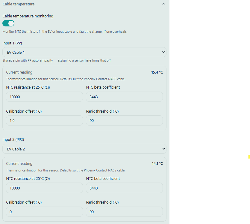
amaan
The third point claims that a missing ground is detected and then the AC relays are switched open to de-energize the system. Am I right in thinking that this feature exists because there can be a case where the protective earth conductor is broken and thus on the event of earth fault the EV can be raised to the touch voltage?
If so, how exactly is this safety checking enabled in the OpenEVSE? Is it in the hardware or simply in software?