CPU
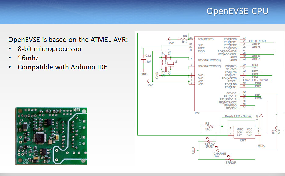
Pilot circuit
The +/- 12v square wave is created by supplying an operational amplifier with a +/- 12v power supply created by the DC/DC converter module from the 12 volt supply. The output of the op-amp is buffered by R1 (which allows the EV to drag the voltage down without unduly straining the output stage of the amp) and fed to the vehicle. The pilot pin is also fed back to ADC1 of the CPU, which allows the CPU to sense the voltage. The CPU will detect the negative portion of the signal not being all the way at -12v as a missing diode condition and will use the measured voltage level (and therefore, the resistance being offered by the EV on the pilot) to select states A through D (EVSE Ready - Not Connected, EVSE Ready - Vehicle Connected, Vehicle requests charging, vehicle requests vent+charge). In stage A, the CPU will set a solid +12v output, and in the other states except state E and F (Error stated output steady -12v).

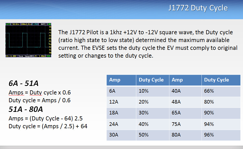
Pilot Duty Cycle
The pilot will output a square wave whose duty cycle represents the current availability setting made in the UI for the current charging mode (L1 or L2). It does this by oscillating PB2 under software control.
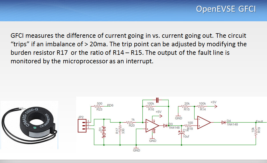
Ground Fault Current Interrupt GFCI or GFI
The Ground Fault Current Interrupt (GFGI) current transformer coil detects any unbalanced current flowing through conductors passing through it. By passing both of the J1772 power cables through it, any current leaked to ground in the EV will result in a differential current within the CT. This will result in a voltage appearing at the input of the OP amp (diode D1 protects against excessive voltage in a run-away leakage event, such as a conductor short to ground). The second OP amp acts as a comparator and will "switch" from a low output to a high output when a threshold is exceeded. This output is fed as a fault indication into the CPU, which will register a ground fault and open the relay.
AC Test
Two AC line monitor channels on an opto-isolators run through diodes and resistors detect AC power on the line to ground. On the v6 and newer hardware one channel is used for Continuous Ground Monitoring from the input AC power. The second channel is on the switched side of the relay used for stuck relay detection. The presence of an AC voltage potential relative to ground on either channel will result in a state change from High to Low appearing on PD3 and PD4 of the CPU. Since the test pins are downstream of the relay, there should be no voltage present (pin state HIGH) the relay is open. This is how the stuck-relay test is accomplished. A lack of voltage on the input channel will result in a ground test failure.
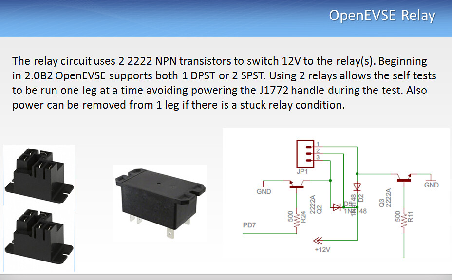
Relay control
The transistor and resistor on PB0 and PD7 are straightforward open-collector switching circuits. The reverse bias diodes across the relay coil protect the transistors from coil collapse voltages when the transistors are turned off.
Safety Checks (PDF Attached Below)
